Sunday, February 28, 2016

Low Power Voltage Sampling

The car computer project has taken a big detour for the last few months in lieu of my gaining more experience with microcontrollers and electronics. Carputer 2015 was mostly a system integration design to be achieved by plugging together existing modules. Carputer 2016 is about integrating complex pre-existing modules with customized sensing, communication, and control. Alas, this probably makes the project even less accessible for those wanting their own carputer. On the plus side, most of the people who hit my blog are finding it via web search. I hope electronics hobbyists can find something of use here.

I've lately been exploring very low power microcontroller applications. There are so many situations that fit the form:

  1. Take a sensor reading.
  2. Process, store, and/or respond to the sensor value.
  3. Sleep until interrupt, then repeat.
Such systems are often deployed with their own, limited power source. My specific application is normally powered via micro-USB with a 5.5V supercapacitor backup. I'd like the controller to monitor both its USB and capacitor voltage to be able to indicate charging, discharging, and out of spec power.

Simply powering a resistive voltage divider could take on the order of 100 microamps. That's actually significant compared to the sleep current of an ATmega328P controller. The typical solution is to switch the high side of the voltage divider with a P-channel MOSFET. The divider (or resistive sensor) can then be powered only for the duration needed to get a stable sample. See the following:

My application is constrained by the number of available connector and controller pins. What I really want is to pulse an analog pin and then read my sample on that same pin. I do this by adding an N-channel FET to momentarily discharge the 0.1µF cap on the P-channel's gate.

FETs with a low gate-source threshold voltage allow this circuit to function down to the 2.7V brown-out of my microcontroller. If you don't need low voltage operation, there are probably cheaper FETs that will work. I'm using a ZVP4424A and a ZVN2106A. As you can see, the sense output is connected to the gate on the N-channel FET. By dividing the output low enough, the gate will stay low/off. A timed low pulse on A0 should further guarantee a reset.

Reading from a µCurrent GOLD show single digit nanoamps when the divider is off and 1+ milliamps (I badly need a scope!) when on and charging the gate cap back up. Mission accomplished!

Thursday, September 24, 2015

Carputer 2015 - September Status

Time rolls on and the car computer has yet to roll. I've been having way too much fun interfacing and developing for Arduino. Still, everything else is ready to go, so expect the rolling demo video and blog post sometime next week. Here's a quick summary of what the system looks like.

Frontend

  • Hardkernel Odroid XU-4
    ARM-based Android computing frontend
  • Software to use network GPSd (TBD)
  • Wired Ethernet link to backend
  • Chalkboard Electronics 7" IPS TFT display w/ touch
  • Blue Microphones Tiki
    USB noise-canceling mic
  • DC switching power converter for Odroid

Backend

  • Raspberry Pi 2
    ARM-based Linux backend and network router
  • Nexus 5 Android smartphone
    USB tethered to Pi for wireless data access
  • Async serial GPS module
    Provides location data to GPSd on Pi
  • Febon100 UVC video capture
    Provides MJPEG over USB video into Pi
  • 12V powered USB hub
    Can feed 5V to Pi and additional power to N5

Management

  • Freaduino Mega2560 (modified Arduino Mega clone)
    System management controller
  • Resistors and analog ICs for voltage and current measurement
  • Adafruit 2675 OLED display module
    For system diagnostics and power monitoring
  • PowerStream 12V DC UPS module
I imagine the Arduino as something of a lights-out management controller for the entire system. The initial use is power monitoring and control. The Cosa software platform has been a wonderful help when developing for 'duino, as an event-driven approach is important to me. Check out my demo of voltage monitoring and text display.

Thursday, September 10, 2015

Getting Intermediate with Arduino

There's a wealth of information out there on getting started with the Arduino microcontroller, development environment, and basic electronics. So you've interfaced with LEDs, sensors, and modules. You've written sketches to do digital input and output, analog input, and maybe a bit with async serial, SPI, and I2C interfacing. Now you're ready for the next step. Maybe you have a project in mind that needs to make that transition from prototype to something that can survive real world conditions.

Now's the time to roll up your sleeves and yank that AVR controller IC, design a custom board, and start developing directly with the avr-gcc toolchain. Wait... what?

This is a fundamental problem with the beginning hobbyist and rapid prototyping nature of Arduino. There are obvious transition paths when you simply need more hardware resources. The Mega 2560, with its abundant I/O, RAM, and flash is clearly more capable than an Uno. The Arduino Due is fast, but may not be worth the loss of compatibility and ubiquity. Once you start exploring the world of custom and specialized 'duinos it's easy to become overwhelmed by the choices. There's no obvious path from beginning experimenter to serious project builder.

Hardware Selection


As I've progressed with Arduino, I've learned which boards to buy by making wrong choices and wasting money. Maybe you won't have to. Here are some general recommendations:

  • Avoid prototyping boards with custom I/O.
    That 'duino with built in Bluetooth or Ethernet may be tempting, but adding I/O modules to standard boards is more flexible and provides useful experience.
  • Choose modules over shields.
    Using multiple shields will eventually lead to pin conflicts. Shields are also constrained by the Uno form factor. Modules can be more easily moved between different types and sizes of controller.
  • Build out your own proto shields or boards.
    Perma-proto shields can be useful to consolidate modules, connectors, and small circuits as you progress from prototyping toward deployment. At some point you'll need to get that tangled mess of prototyping wires, modules, and components into a more compact, organized, and ruggedized form factor. Perma-proto shields are a decent way to customize interfacing for your project.
  • Plan your prototyping and deployment requirements.
    Determine early your physical requirements and controller specifications for both prototyping and deployment. That Uno or Mega might be great for prototyping, but not quite cut it for deployment in tight spaces or harsh conditions.
  • Select boards in pairs.
    To progress from prototyping to deployment you're better off with two (or more) controller boards. I'm currently liking the compatibility of prototyping on the Uno and deploying on the Adafruit Pro Trinket. You can build your own little shields to stack on the Trinkets.
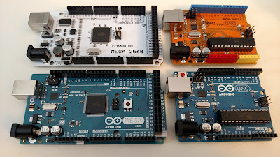
A sampling of prototyping boards.

Software Development


The Arduino development app is great for beginners. For actual software development it's extremely limited. Yet again the intermediate developers are left to fend for themselves. All the thirdparty libraries and examples are written to be used from the standard IDE and runtime that are borderline unusable for production software.

I probably don't need to explain what's wrong with the Arduino IDE. It's simply extremely limited when compared to environments like Eclipse. That said, it's not unbearable to continue using the Arduino IDE for your .ino projects and use a better editor or complete IDE to organize most of your functionality into libraries.

The real problem with Arduino development is that the libraries and runtime are awful. The AVR microcontroller underlying most 'duinos doesn't typically run an operating system with processes and threads as you would find on a single board computer like the Raspberry Pi. Your Arduino project and supporting runtime library are your operating system!

The standard runtime works if you're only trying to do a very limited number of things and don't require fast real-time response. The fundamental problem is the linear nature of the standard runtime and libraries and the acceptance of millisecond level delays. It's simply unacceptable that library routines block the execution of other code for many thousands of instructions. What is needed is an asynchronous programming approach with asynchronous I/O, events/callbacks, and timers. This approach can prevent missed I/O events, allow events to happen at predictable times, and still allow the controller's processor to sleep when it's not needed.

The frustrating nature of standard Arduino development almost caused this experienced software developer to abandon Arduino entirely. Fortunately someone else who had experienced these same problems made the effort to do something about the situation. Enter Cosa, "An Object Oriented Platform for Arduino Programming."

Getting into Cosa takes a bit of time, but I strongly recommend taken the plunge as early as possible. Dive in there and start converting libraries to fit the framework of Cosa helper classes. Arduino was screaming out for asynchronous OO development and Cosa is what exists and works.

Furure Directions


So where does the intermediate developer with a couple projects under the belt go next? I can only speak from my own experience. With the availability of tiny 'duino boards, I don't feel a strong impulse to design custom controller PCBs when I can stack or socket existing boards. With Cosa I don't currently feel the need to develop directly with the avr-gcc toolchain. I've found an environment where I can get things done.

Would I step up to the ARM-based Arduino Due for more demanding projects? Probably not as things currently sit. Either arduino.cc, arduino.org, or Adafruit would do well to negotiate with Mikael Patel to embrace and enhance the Cosa environment while extending it to the Due board. Without a solid software ecosystem that can work for beginning, intermediate, and advanced developers, Arduino seems destined to become yet another legacy embedded platform. Tick, tock, Arduino. The TI LaunchPad is looking really tempting right now...

Tuesday, September 8, 2015

DC Power Conversion

With so much interest in mobile electronics these days, Makers are tossing aside their long despised AC adapters and turning to DC power. Unfortunately, DC sources tend to fluctuate or be comprised of cells that produce voltages not directly usable by most electronics. It's relatively easy to reduce voltage by converting electrical energy to heat, but it's hard to find applications where efficiency isn't a factor. Efficient switched power conversion is gradually replacing inefficient linear voltage regulation.

Terminology


It's useful to know a few terms to understand the type of voltage conversion performed by devices.
  • Linear voltage regulation / conversion. A continuously regulating voltage divider (inefficiently) down-regulates voltage.
  • Switching voltage conversion. Current is rapidly switched to step voltage up or down.
  • Buck converter. This is a switching converter that reduces voltage to a desired level. In some converters the output voltage may be configurable but it will always be less than the input by some margin.
  • Boost converter. This is a switching converter that raises voltage to a desired level. A common use would be running 5V electronics from a 3.7V Li-Ion or Li-Po battery.
  • Buck-boost converter. This flexible switching converter can either raise or lower voltage to match the desired output.
A sampling of fixed and variable voltage converters.

Real World Examples


So let's say we want to power a tiny computer like the Raspberry Pi or a microcontroller board like Arduino from a 12V source.


Raspberry Pi


The Pi requires regulated 5V input through its Micro USB power connector. This allows the use of ubiquitous AC to Micro USB charging adapters and eliminates the need for a 5V regulator on the Pi. In hindsight, these were very questionable choices. Many existing chargers could not supply sufficient current for the Pi, and no onboard 5V regulation makes the Pi harder to run directly from a DC source. This has all been a big enough problem that there are now quite a few DC to 5V power boards designed to meet the specific requirements of the Raspberry Pi.

With the USB connector unplugged there seems to be no problem supplying regulated 5V power directly through the Pi's 5V header pin.

This Pi 2 works great off a tiny buck converter.

I'm happily running my Pi 2 using the tiny Adafruit "UBEC" buck converter pictured above. It's almost like the connector was specifically intended to provide power directly to the 5V rail of the Pi. (It almost certainly was.)

Arduino


Most Arduinos and clones are pleasantly flexible regarding DC input. The USB connector can be used to supply regulated 5V. The 2.1mm barrel jack is specified to accept 7-12V which is passed through a linear regulator to provide 5V. Considering what we know about linear regulators, it's better to stick toward the lower side of that range. A small number of 'duinos, like the Freaduino Mega2560 pictured below, feature an onboard switching regulator that can handle more than 20V. Finally, a regulated 5V supply may be tied to the internal 5V rail via the header pin.

Exotic "Freaduino" with onboard switching regulator.

I specifically sought out and bought my Freaduino so I could pass 12V (automotive) power into the barrel jack with minimal losses. Given a more typical 'duino, a variable buck converter set to ~7V and passed into the barrel jack would be a fine approach.

Odroid


Although not as popular as the Pi and 'duinos, the Odroid is a very capable yet inexpensive tiny computing platform. Please refer to my writeup on the new ODROID-XU4. This Odroid specifies power requirements as a beefy 4A of current at 5V. A fixed 5V 5A buck converter did not result in a stable system. The AC adapter output measures 5.15V with no load. The fixed 5V converter either droops enough under load or 5V isn't quite enough to stably run the Odroid. Fortunately I had a DROK 5A adjustable buck converter that worked flawlessly when set to 5.2V. I may actually write a review of this converter, as it has some interesting features. These include limited rate battery charging and voltage and current monitoring over an asynchronous serial interface.

Friday, July 31, 2015

Carputer 2015 - ODROID-XU4 SBC

The carputer project is still ongoing, just vanished down a rabbit hole for a few weeks. As it turns out, the Android OS environment is simply more compatible, stable, and easier to manage on ARM platforms than x86 PC platforms. Duh, right?

The Carputer is Dead, Long Live The Carputer!


The Carputer 2015 frontend is now powered by a US$74.00 ODROID-XU4. This capable little board contains, at its heart, the same Exynos 5422 SoC as the international variant of the Samsung Galaxy S5 smartphone. This places it a notch below 2015's flagship devices, but in a completely different class than low-cost boards like the Raspberry Pi 2 and BeagleBone Black.

Hardkernel ODROID-XU4 ARM SBC

Ordering the Odroid and accessories from ameriDroid went flawlessly. The order arrived quickly, well-packaged, and complete. There was even a little handwritten "thank you" note. Other Asian manufacturers would do well to emulate Hardkernel's American distribution channel.

What's on (the) Board?


It should be evident from the picture that there's a lot of I/O on this little board. So here's what we have:
  • Samsung Exynos 5422 SoC, 8 cores, 2 GB, graphics
    AnandTech provides some quick analysis and comparison.
  • Heat sink and fan
    The PWM-controlled fan kicks in as needed. I have yet to see it move.
  • Power switch
    Pulls the board out of sleep state. The board powers on automatically.
  • 2x USB 3.0 host ports
    These share an internal 2 port hub.
  • 1x GigE Ethernet port
    A wonderful and rare feature for ARM SBCs! Internally, this runs off a dedicated USB 3.0 channel.
  • 1x USB 2.0 host port
    Is this connected via an internal hub? Directly connected, no hub.
  • Full-size HDMI connector
    Nicely enough, this supports digital audio output and CEC.
  • DC power jack
    Input is specified as 5V at up to 4A. 4 amps is a lot for a small board.
  • Standard microSD card slot
  • Connector for eMMC module (underside of board)
    This supports fast 5.0 modules!
  • Boot selector switch (microSD or eMMC)
  • Serial console connector (requires cable)
  • Connector for RTC battery
    Nicely done to leave the battery off the board but easy to add!
  • Headers for digital, analog, and bus I/O
Hardkernel did a great job with the design of this board. Pretty much everything is there, and in a form that doesn't require adapters. It does bear mentioning the few features that are missing:
  • No analog audio in/out
    Digital audio is supported via HDMI, USB, and I2S headers.
  • No wireless anything
    You'll need to add WiFi, Bluetooth, GPS, etc. if you want them.
  • No USB client port
  • No power monitoring or battery management
    Some other models of Odroid have power monitoring.
Again, it was a logical choice to leave out noisy radios and audio conversion.

What about Android?


Hardkernel sells eMMC modules and microSD cards preloaded with Android or Linux. Currently shipped versions appear to be Android 4.4 KitKat and Ubuntu 15.04. Disclaimer: I have not yet tried Linux on Odroid. Android images appear to be customized versions of CyanogenMod. After playing around a bit with 4.4, I soon upgraded to the community supported 5.1 and installed the Google Apps.

The carputer plan is to use HDMI audio output and a USB microphone. Digital audio was one of those things that just didn't want to work on Android-x86. I have a Blue Tiki USB microphone that is quite good at filtering noise from voice input. This mic also provides a (semi-useless?) output channel that confuses the Android audio subsystem. This results in USB audio in or HDMI audio out, pick one. Thankfully this has a quick solution under Android 5.x. Editing the audio_policy.conf file to comment out the USB audio output section gave the desired result. Multiple audio device support remains problematic in Android.

The long-promised in-car demo shouldn't have to wait much longer!

Monday, May 18, 2015

Carputer 2015 - Sourcing Parts

When I began this car computer project, I imagined that the current popularity of hobbyist embedded computing and custom A/V projects would make it easy to obtain components. Not so much. Internet searches and scouring forums can lead toward the specific products that will work best for a project, but many of these products will not be available from a domestic distributor.

Be prepared to work directly with distributors in Asia. Some of these distributors may have a web site for ordering, some work through eBay, and some just have an email address. It helps to respect that English is not the first language and to keep communication simple and clear. Payment is generally accepted through PayPal and timely shipping may cost a bit. I have so far dealt with four different Asian distributors and have received correct and functioning components each time.

Expect a lot of parcels like this one.

The apparent cheapest solutions to problems may not actually be the cheapest. One of my initial project guidelines was to start with inexpensive components and be able to justify price increases. Having done this, I can now offer advice to others who may be considering a similar project.

  1. Don't buy an EasyCAP / EzCAP for composite video capture from Linux. You could spend a fortune in money, time, and frustration to get a combination of device and kernel that actually works. Spend the money and get a UVC capture device from +Andy FEBON.
  2. Don't settle for a cheap TN display panel or resistive touchscreen overlay. An IPS panel with capacitive touchscreen gives the true "tablet experience" that most people expect. I finally found what I was looking for at Chalkboard Electronics.
Left good (FEBON100 UVC), right bad (EasyCAP).

The US$56 TN panel and resistive touchscreen setup below is pretty much only useful for prototyping. I certainly wouldn't want to have to use it.

Cheap TN panel and resistive touchscreen.

Below is the 7" IPS panel that I will install in my car. The pictures don't do it justice. The display controller is small and affixed to the back of the panel. Entire unit can be powered over USB! Full information here.

IPS panel in direct lighting.
IPS panel in indirect lighting.

I'm now just waiting on a powered USB3 hub and some cables before being able to demo this system in my car. A number of commenters have mentioned that it's hard to grasp what I'm trying to achieve with this project. My next posting should contain a demo video that makes things much more clear.